

Top Cleanroom Engineering Strategies for High-Performance Controlled Environments
2026-10-07
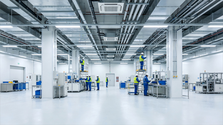
Cleanrooms don't fail because of tight budgets—they fail because the right engineering strategies never made it into the design. If you're chasing ISO compliance or pushing for a high-performance controlled environment, the difference between mediocrity and excellence often comes down to a handful of overlooked details. From airflow patterns to material selection, the choices you make before construction can save you years of headaches—or create them. At GENO Pharmatech, we've seen how the right strategies transform sterile spaces into reliable production assets. In this post, we'll break down the top cleanroom engineering strategies that actually move the needle, so you can avoid the usual pitfalls and build an environment that performs as well as it looks on paper.
Airflow Design That Works When the Power Dips
Most airflow designs assume steady power, but real grids flicker, sag, and occasionally drop out. A design that survives these dips starts with the fan curve itself. Instead of picking a fan that only hits its sweet spot at nominal voltage, choose one with a flat efficiency plateau across a wider range of static pressures. That way, when input voltage sags by ten or fifteen percent, the fan doesn't stall or surge—it just shifts slightly along its curve. Pair this with a motor controller that has built-in undervoltage ride-through, not a basic soft starter. The controller should hold the fan at a minimum safe speed during brief brownouts, then ramp back up smoothly once power returns. This prevents the classic startup slam that tears ductwork and trips breakers.
The second layer is about airflow path resilience. Dampers and backdraft shutters should default to a position that maintains natural convection when the fan slows. In many systems, a power dip causes motorized dampers to spring shut or hang half-open, creating a sudden pressure imbalance. Use weighted or spring-return dampers calibrated to the minimum ventilation rate. Also, oversize the duct cross-section by roughly twenty percent beyond peak demand. That extra volume acts as a buffer—during a short power sag, the air already in the ducts keeps moving under residual momentum, smoothing out the transition. It’s a passive trick, but far more reliable than trying to make the fan react faster than the grid allows.
Finally, don't ignore the acoustic and structural side. When power dips, fans often run at a non-optimal blade-pass frequency, triggering resonance in light-gauge duct walls. A design that works through dips includes vibration isolators tuned for a broad frequency range, not just the nominal RPM. And the fan housing itself should have a small inertial flywheel or heavy-duty rotor—just enough rotating mass to bridge a two- or three-second brownout without speed hunting. Combined, these choices make the difference between a system that stumbles and one that quietly keeps moving air until the grid recovers.
The Pressure Cascade Trap Most Renovations Ignore
Renovators fixate on finishes and floor plans while a quieter force undoes their work: pressure differentials between rooms, floors, and the exterior. When walls get tighter but exhaust fans, range hoods, and dryer vents keep pulling air out, the house goes negative. That negative pressure drags in air from wherever it can—crawlspaces, wall cavities, attached garages—carrying moisture, insulation fibers, and combustion byproducts into living spaces. The cascade begins small, a bathroom door that drifts shut or a whistling window, but it compounds into rot and air quality failures that no coat of paint can hide.
The trap deepens when a renovation seals one zone without rebalancing the whole. Add a dedicated home office with a return-air path blocked by a new door, and supply air piles up while the adjacent hallway starves. Open-concept builds are just as vulnerable: a high-ceilinged addition changes the stack effect, so upper floors pressurize in winter while the lower level pulls soil gas from below the slab. Most contractors never measure this with a manometer, so the problem stays invisible until it shows up as condensation on windows, musty closets, or a carbon monoxide alarm that won't stop tripping.
Fixing it demands thinking in terms of airflow architecture, not just building code. That means commissioning the envelope after every change—checking room-to-room pressure with doors closed, verifying makeup air for exhaust appliances, and adding transfer grilles or jump ducts where pressure imbalances exceed a few pascals. It's unglamorous work that rarely makes the highlight reel of a renovation reveal, but it's the difference between a house that merely looks renovated and one that breathes without pulling itself apart.
Cleanroom Materials: Specifying for Chemical Resistance, Not Just Cleanability
Cleanroom material selection often gets narrowed to a single question: how easy is it to wipe down? That focus misses a more damaging failure mode. Repeated exposure to disinfectants, solvents, or process chemicals can degrade a surface long before it looks dirty. Stress cracking in polycarbonate, softening of acrylic, or leaching from certain elastomers can release particles and volatile compounds that compromise the cleanroom environment. A spec that ignores chemical resistance is essentially building in a future contamination source.
Common cleaning agents like isopropyl alcohol, hydrogen peroxide, and quaternary ammonium compounds do not affect all materials equally. Polycarbonate, for instance, can craze or crack under alcohol contact, while many grades of acrylic become hazy or brittle. Stainless steel and fluoropolymers such as PTFE and PVDF generally hold up well, but their cost and fabrication constraints mean you cannot simply default to them. The practical approach is to build a chemical compatibility matrix based on the exact agents, concentrations, and contact times used in your facility, then test candidate materials under those conditions rather than relying on a generic cleanroom-compatible label.
Chemical resistance also needs to be written into the material specification, not treated as an afterthought during installation. Ask suppliers for immersion or wipe test data, and pay attention to temperature because chemical attack accelerates with heat. After exposure, look for surface changes that are easy to miss: whitening, tackiness, micro-cracks, or loss of gloss. These are early warnings that the material is generating particles or extractables. Including chemical exposure limits in the user requirement specification and scheduling periodic material inspections will catch degradation before it affects product quality.
Why Your Particle Counter Misses the Real Contamination Story
Particle counters are often treated as the final word on cleanroom health, but their readings can be dangerously narrow. Most units sample air from a single point for a short burst, then extrapolate that snapshot across the whole room. What they miss is the slow drift of contamination that builds in dead zones—behind equipment, under workbenches, or near door seals—where air changes per hour don't tell the full story. A counter might show five particles per cubic meter while a sticky surface two meters away is quietly accumulating a biofilm that will become next week's excursion.
The real contamination narrative also unfolds on surfaces and in liquids, domains where airborne particle counts are practically blind. A vial filling line can pass every air sample yet still suffer from dripping condensate or a cracked gasket shedding fibers. Relying on particle counts alone is like checking the weather by tasting one raindrop: you learn something, but not whether the storm is already inside. Contamination events usually start as a surface or personnel issue, then become airborne only after disturbance—often long after the counter has logged a clean bill.
To see the real story, you need to pair instantaneous counts with trend data, microbial settle plates, and contact sampling. A sudden spike is rarely the beginning; it's the visible echo of an earlier failure. When operators trust only the counter, they optimize for the metric instead of the environment—wiping down the sample port while mold grows in the HVAC drain pan. The instrument misses what it was never designed to see, and by the time the count rises, the contamination has already written its own ending.
Humidity Control as a Contamination Strategy, Not an Afterthought
When humidity is treated as an afterthought—something checked only after a problem appears—facilities invite invisible risk. Moisture doesn't need visible condensation to support microbial growth; it thrives in microclimates where relative humidity hovers above 60% near cool surfaces, inside ductwork, or behind stored materials. Instead of chasing humidity spikes reactively, forward-thinking teams map the building's moisture dynamics first. They identify cold spots, dead zones, and damp corners that never dry fully, then design humidity control around those realities. This shifts the conversation from “fixing a humidity issue” to preventing one from ever taking root.
A proactive humidity strategy ties directly into contamination control by treating water vapor as a potential vector, much like particulate or chemical contamination. For example, in food processing, a drop in dew point can turn a clean conveyer line into a condensation trap, dripping onto product surfaces. In pharmaceutical storage, fluctuating humidity can activate spore germination in cardboard packaging, creating a contamination source that no amount of surface cleaning resolves. By setting moisture-specific limits per zone—not just a single building-wide RH setpoint—teams create a living barrier. They monitor both absolute humidity and surface temperatures, so the system flags when conditions approach the dew point, not after the fact.
Making humidity a first-class contamination strategy also means integrating it into daily operational rhythms rather than relegating it to HVAC maintenance logs. Operators should be trained to read moisture trends alongside microbial counts, understanding that a sudden drop in outside air humidity might be as telling as a positive swab result. The goal is not simply drier air, but stable, predictable moisture conditions that starve contamination pathways. When humidity control is designed in from the start—embedded in layout decisions, material choices, and airflow patterns—it stops being a hidden afterthought and becomes an active, measurable line of defense.
Building a Cleanroom That Can Change Processes Without Re-Qualification
Most cleanroom projects are locked into a single process from day one. The air handling, the materials, the layout—everything is tuned for one specific operation. When that operation changes, even slightly, the room often fails to meet particle counts or pressure differentials. Re-qualification becomes a costly, time-consuming ritual that no one wants to repeat. But a cleanroom can be designed differently. By decoupling the critical parameters from the process itself, you create a space that adapts without triggering a full re-validation.
The key is to build flexibility into the infrastructure rather than the process. Instead of hard-wired fan filter units spaced for one airflow pattern, use modular ceiling grids that allow quick repositioning. Choose wall panels that can be removed and reconfigured without cutting or sealing new joints. Run utility chases with spare capacity and accessible shut-offs, so adding a new tool or changing a chemical line doesn't require opening the clean envelope. And most importantly, set your cleanroom classification based on the worst-case scenario you might reasonably expect, not the exact current need. A Class 100 (ISO 5) room that only runs at Class 10,000 (ISO 7) most of the time has massive headroom for process shifts.
Of course, change management still matters. But if the cleanroom is built to accommodate variation by default, then a process change becomes an engineering adjustment rather than a qualification event. You might swap a wet bench for a plasma etcher, adjust the airflow in one corner, and document the change with a simple deviation report—not a full re-certification. This approach does require more thoughtful upfront design and a slightly higher initial cost, but it pays back quickly when product lines evolve or new clients demand different specs. In the end, the cleanroom stops being a rigid container and starts behaving like a tool that works with your process, not against it.
FAQ
Unidirectional airflow, often achieved through laminar flow designs, sweeps particles away from critical zones in a single direction rather than allowing turbulent mixing. In high-performance cleanrooms, this approach ensures that contamination generated by personnel or equipment is immediately carried toward low-wall returns, keeping the work area cleaner for longer periods and reducing the risk of micro-eddy currents that trap particles near sensitive processes.
Pressure cascades rely on maintaining a consistent differential—typically 10 to 15 pascals between cleanliness classes—with the highest pressure in the most critical area. The key is not just the setpoint but the stability: rapid door movements or inadequate HVAC response can cause momentary reversals. Optimizing involves sizing pressure-balancing dampers correctly, using fast-acting VAV systems, and limiting door openings through interlocking or airlocks. This creates an invisible barrier that continuously pushes air outward from cleaner to less clean spaces.
Materials directly influence particle shedding, outgassing, chemical resistance, and cleanability. A wall panel that appears smooth may have microscopic pores or seams that harbor microbes or release volatile compounds under cleaning agents. High-performance cleanrooms favor non-porous, low-outgassing materials like fiberglass-reinforced plastic or powder-coated steel with sealed joints and radiused corners. This reduces the surface area where contaminants can accumulate and simplifies disinfection, ultimately lowering the bioburden and improving process reliability.
Higher air change rates dilute and remove contaminants faster, but they also drive up fan energy and cooling loads substantially. A balanced strategy involves using computational fluid dynamics or airflow visualization to identify actual particle sources and then tailoring air change rates to those zones rather than applying a uniform high rate everywhere. Demand-based control—where air change rates temporarily increase during high-activity periods or when particle counts exceed thresholds—can maintain cleanliness without wasting energy during idle times.
Staged filtration typically uses pre-filters to capture large particles, intermediate filters to extend the life of final HEPA or ULPA filters, and terminal filters at the point of delivery. This protects the final filters from premature loading and prevents contamination from re-entering after the air handler. In high-performance settings, terminal HEPA filters should be located as close to the clean zone as possible—ideally in the ceiling grid—to minimize the risk of leakage in downstream ductwork and ensure that the delivered air meets the required class at the point of use.
Real-time monitoring of particle counts, differential pressure, temperature, humidity, and even microbial settling rates provides early warning of drifts before they become excursions. Instead of relying solely on periodic certification tests, continuous data allows engineers to detect patterns—such as increased particle levels during shift changes or after specific equipment cycles—and make proactive adjustments. This shifts the cleanroom from a static facility to a dynamically managed environment where performance is validated continuously rather than assumed between audits.
Engineering design can make gowning a physical part of the contamination control chain. For example, designing gowning rooms with staged zones—from street clothes to cleanroom garments—and placing sticky mats or air showers at transitions encourages compliance. The layout can direct personnel flow so that no one can bypass the gowning area. Additionally, providing adequate space, proper lighting, and ergonomic benches reduces the likelihood of improper gowning. When the facility itself enforces the protocol through flow paths and interlocked doors, human error is significantly minimized.
Commissioning should go beyond basic particle count tests. It includes airflow velocity mapping, filter integrity scans (DOP/PAO testing), pressure differential verification under dynamic conditions, temperature and humidity uniformity tests, and recovery rate tests where the room is deliberately challenged with particles and timed to see how quickly it returns to class. Light intensity, noise levels, and vibration checks are also important for sensitive processes. Most importantly, validation must be performed with equipment running and personnel present in typical numbers, because static certification often masks real-world performance issues.
Conclusion
High-performance cleanroom engineering starts by acknowledging that normal operating conditions are only half the story. Airflow design must hold up when utility power sags or a fan ramps down; otherwise, pressure differentials can reverse and send cleanroom air into less controlled zones. Renovations frequently miss this pressure cascade trap, leaving gaps at doorways or pass-throughs that compromise isolation. Material selection needs to go beyond cleanability, focusing on chemical resistance against disinfectants and process solvents that can craze polymers or oxidize metals, creating hidden particle reservoirs.
Particle counters give a snapshot, but they often miss transient contamination events or particles outside their calibrated size range, so they should be paired with airflow visualization and surface sampling for a fuller picture. Humidity control deserves equal weight: high humidity encourages microbial growth and condensation, while overly dry air increases static charge and particle adhesion. Finally, designing for flexibility—movable partitions, pre-wired utility drops, and zoning strategies—lets a cleanroom adapt to new processes without triggering full re-qualification, saving time and preserving operational continuity.
Contact Us
Contact Person: Amy Yang
Email: [email protected]
Tel/WhatsApp: 008619330882686
Website: https://www.genopharmatech.com/