

Top 10 Forged Steel Globe Valves for Reliable Industrial Flow Control
2026-11-16
Choosing a forged steel globe valve often looks easy on paper—right up until thermal cycling, abrasive media, or constant throttling exposes weak seats and sloppy stem sealing. This roundup cuts through catalog clutter to highlight ten valves that actually deliver reliable flow control, with attention to pressure-temperature limits, trim options, and ease of in-line maintenance. Along the way, we also look at several CRXV configurations that have proven useful in demanding process loops. Whether you are replacing a chronic leaker or standardizing a new line, these picks offer a practical shortlist.
Forged Steel Under Pressure and Where Its Strength Actually Comes From
The phrase “forged steel under pressure” gets thrown around a lot, but the real story is less about toughness as a buzzword and more about what happens to the grain structure when a billet is squeezed into shape at high temperature. Instead of simply being melted and poured, the metal is worked while still hot, forcing the internal crystals to elongate and re-form along the lines of greatest stress. That directional flow is what separates a forged part from a cast one: the material isn't just hard, it's oriented to resist cracking along the exact paths where load will actually hit.
Pressure alone doesn't create that strength, though. Temperature control matters just as much. If the steel drops below its forging range mid-process, you get surface tears and internal micro-fractures that no amount of later heat treatment can fully erase. The best shops watch the color of the metal like a cook watches a steak, working it only while it's in that narrow band between too brittle and too soft. It's a slower, more expensive way to make a component, and that's why forged parts often end up in steering knuckles, crankshafts, and high-pressure valve bodies—places where a hidden flaw isn't just a warranty claim, it's a genuine hazard.
What often gets missed is that the strength isn't uniform. A forged bar is stronger along the direction it was hammered, but slightly weaker across it. Engineers who understand this will orient the grain flow to match bending or torsional loads, essentially treating the steel like wood with a preferred split line. That deliberate asymmetry is why two parts with identical chemistry and hardness can behave completely differently in service. It's not magic, and it's not just “pressure.” It's geometry at the grain scale, decided before the first hammer blow.
Nailing the Pressure and Temperature Range Before It Nails Your Process
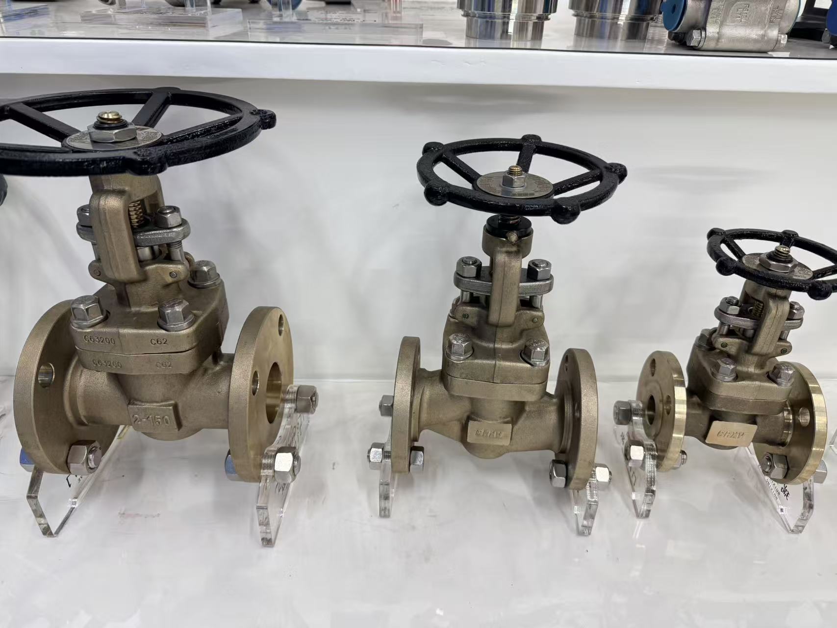
Pressure and temperature limits usually get treated as a pair of fixed numbers on a specification sheet, but the real problems begin when those values drift just outside the expected band and no one catches it until a batch loses clarity or a seal starts weeping. It is rarely one violent spike. More often it is a slow shift caused by a wearing steam valve, a lagging sensor, or a cooling loop that runs warmer than the gauge indicates. Knowing the range means observing the process across an entire shift, not trusting what the original design predicted.
A common misstep is borrowing an operating window from a similar line and assuming it will transfer. Ambient temperature changes, pressure drops through piping, and even the location of a probe can distort the effective limits. If the upper temperature boundary was established without accounting for heat held in the jacket, the system may be running much closer to the edge than it appears. Mapping these offsets under normal production load separates a stable window from one that only works during a quiet afternoon run.
The range also needs to be revisited after any change in raw materials or after maintenance alters the mechanical setup. A new pump curve, a higher viscosity feed, or a rebuilt clearance can all shrink the safe operating band. Once the true limits are mapped, operators rely less on manual overrides and more on control settings that actually hold. That shift is what keeps pressure and temperature from quietly dictating downtime and scrap.
Seat and Disc Material Pairs That Decide How Reliable the Seal Stays
A valve's sealing reliability rarely hinges on a single component. More often, it depends on how the seat and disc materials behave together under pressure, temperature swings, and repeated cycling. Pairing a hard disc with an overly soft seat can lead to premature indentation, while two hard surfaces may struggle to conform tightly enough to prevent leakage. The real question is whether the pair maintains a consistent contact geometry over time, not just whether each material looks durable on a datasheet.
Consider the way thermal expansion rates interact. A metal seat and a similarly expanding metal disc might stay aligned during heating, but a polymer seat against that same disc could soften, creep, or lose compression. Conversely, a resilient seat can compensate for slight disc misalignment at ambient temperatures, offering a forgiving seal that a rigid metal-to-metal setup cannot match. The successful pair is the one that tolerates the most punishing condition in the actual service, not the one that wins on hardness alone.
Field experience often reveals that modest material combinations outperform exotic ones simply because they degrade predictably. When a seat and disc wear together at a similar rate, the sealing line shifts gradually instead of failing suddenly. That predictability lets maintenance teams plan interventions before leakage becomes critical. In the end, reliability is less about selecting the strongest materials and more about engineering a pair whose failure modes are slow, visible, and manageable.
When a Globe Valve Still Beats a Ball Valve for Throttling
Ball valves earn their reputation in on-off service, but throttling pushes them into territory where small movements of the handle produce large, uneven changes in flow. A standard ball valve has a flow characteristic that bunches most of its control range into the first 30 to 40 degrees of opening, leaving the rest of the travel with little practical effect. Globe valves move the disc perpendicular to the seat, so the relationship between stem travel and flow is far more predictable. That matters when an operator needs to hold a setpoint without constantly chasing it.
Wear is the other factor that quietly works against a throttled ball valve. At partial opening, the fluid tears past the edge of the ball and concentrates on a narrow band of the seat, which can cut grooves into the sealing surface and lead to leaks long before the valve should need service. A globe valve spreads the pressure drop across the seat and disc, and its internals are built to handle repeated partial-stroke operation. In steam, high-pressure water, or any line where the valve will spend hours at 20 to 50 percent open, the globe pattern simply lasts longer between repairs.
There are cases where a characterized ball valve or a V-port ball can do the job, especially in clean, low-pressure lines that only need coarse adjustment. But when the process demands fine control under a steep pressure drop, frequent movement, and a valve that will not become a maintenance headache, the globe valve still holds its ground. It is not about one design being older or newer; it is about matching the internals to the actual duty.
Installation Habits That Keep a Forged Steel Globe Valve from Failing Early
Most early globe valve failures trace back to how the valve met the pipe. Forged steel bodies are tough, but they will not forgive a misaligned flange gap that gets pulled shut with bolt torque. Before any bolts go in, check that the mating flanges sit parallel and the studs slide through without prying or forcing. If you have to use the bolts to close a gap, the body is already under stress it was never meant to carry. That stress concentrates around the bonnet joint and seat area, which is exactly where leaks and cracks tend to show up later.
Support the pipe on both sides so the valve is not doubling as a pipe hanger. A common shortcut is to let a heavy upstream spool rest on the valve while the downstream support is adjusted. Forged steel is strong, but sustained bending load can distort the seat geometry enough to cause uneven wear and premature loss of shutoff. Temporary supports during fit-up are cheap compared to pulling a leaking valve out of service after a few months.
Finally, respect flow direction and keep the internals clean. Globe valves are directional for a reason: installing one backwards can make closing difficult and accelerate seat erosion under high pressure drop. Even a small piece of weld slag or thread tape left in the line can wedge between the disc and seat, turning a routine first stroke into a scored seating surface. Blow down the line, confirm the arrow on the body, and tighten the bonnet only after the pipe alignment is proven.
Reading Between the Lines of Supplier Spec Sheets
Supplier spec sheets tend to showcase headline numbers under narrow, carefully controlled conditions. The same part may behave very differently once temperature, supply voltage, or load deviates from those ideal points. Look for what is not stated explicitly: a wide output range might only hold at room temperature, or a current rating may depend on forced-air cooling buried in a footnote. Ask whether the test circuit matches your operating environment before trusting the boldest figure on the page.
Pay attention to how a parameter is defined, not just the number next to it. A signal-to-noise ratio quoted with A-weighting is not the same as an unweighted measurement. A response time stated as "typical" leaves room for parts that are slower but still inside an undisclosed distribution. Small print around measurement bandwidth, settling time, or duration of load can reveal where the supplier has quietly relaxed the conditions.
Graphs are often more honest than summary tables, but only if you read their axes and limits. Curves may stop just before the point where performance falls off, or a logarithmic scale can make instability look gentle. When two sheets appear comparable, dig into the test setup, pulse width, duty cycle, and temperature coefficient. Those details often explain why one part costs less or why a design that passes on paper misbehaves after assembly.
FAQ
Forging aligns the grain structure and removes internal voids, so the body holds up better under thermal cycling and high pressure. In sizes from half-inch to two-inch, that translates to fewer leak paths and a longer service life than a comparable cast body.
Most units in this group are rated to ASME Class 800 or Class 1500. Class 800 covers a lot of steam, gas, and hydrocarbon work, while Class 1500 is the better pick for severe service where pressure spikes and temperature swings are routine.
Look for an integral hardfaced seat rather than a pressed-in ring, and a disc with Stellite or similar cobalt-based overlay. That combination resists wire drawing and steam cutting far longer than untreated stainless trim.
You will see them on steam distribution, blowdown lines, chemical injection skids, high-pressure gas manifolds, and oil processing streams. They are most useful where flow needs throttling or frequent shutoff rather than simple open/close duty.
It matters a lot. A bolted bonnet with an outside screw and yoke keeps the stem threads away from the process fluid, and a backseat lets you repack the gland while the valve is open. Graphite or PTFE packing with a live-load option helps stop fugitive emissions.
Expect threaded, socket-weld, butt-weld, and flanged ends. Forged steel globe valves typically run from 1/2 inch through 2 inch, with some manufacturers extending to 3 or 4 inch in class 800 designs.
Yes, several high-end versions offer a bellows-sealed bonnet for services where leakage cannot be tolerated, such as toxic or expensive media. The bellows adds initial cost but sharply reduces packing maintenance and leak risk over time.
Conclusion
Forged steel globe valves earn their place in demanding services less because they look heavy and more because the forging process aligns grain structure in a way cast bodies rarely match. That gives the body a kind of ductile toughness under pressure spikes and thermal cycling. Still, choosing the right valve means checking the actual pressure and temperature envelope instead of trusting a generic class rating, and paying attention to seat and disc material pairs. A hard disc against a soft seat may seal tightly at first, but it can gall or embed debris; a matched metal pair often lasts longer in steam or high-velocity flow. When throttling is the real job, a globe valve usually remains the better tool than a ball valve, since the plug and seat control the flow path without exposing the sealing surfaces to the full blast of a partially open port.
Installation habits decide whether any of that design work survives. Piping misalignment, weld spatter, or using the valve as a lifting point can distort the body and shorten seat life before startup. Clean assembly, proper support, and gradual warm-up do more than most people expect. It is also worth reading supplier spec sheets with a skeptical eye. Many list pressure ratings and materials but omit cycle life, leakage rates, or whether the trim was tested together. Requesting actual Cv curves and heat traceability separates a genuine industrial control valve from a commodity item with a forged label.
Contact Us
Contact Person: TIM
Email: [email protected]
Tel/WhatsApp: 8615857807381
Website: https://www.crxv.com/en/