

Servo Motor Magnets Manufacturer Explains Magnet Selection for Optimal Performance
2026-09-06
Ask any motion control engineer where servo motors lose their edge, and the answer rarely points to the control loop—it points to the magnets. Choose the wrong grade, coating, or temperature rating and you’ll see drift, demagnetization, and field failures that no tuning can fix. At DAWA, we manufacture servo motor magnets and know that optimal performance starts long before assembly: it starts with matching magnetic properties to real operating conditions. In this post, we’ll share the selection criteria that separate reliable designs from costly re-spins.
Rare Earth or Ferrite? Let Torque Requirements Decide
Choosing between rare earth and ferrite magnets often starts with a simple question: how much twisting force does the application actually demand? Rare earth magnets pack a much higher energy product, so they deliver serious torque from a compact rotor. If your design has tight space constraints or needs rapid acceleration, that extra magnetic punch is hard to beat. Ferrite, on the other hand, generates less torque per unit volume but remains far more cost-effective and thermally stable, making it a sensible choice for steady, moderate-load operation.
Rather than defaulting to one material, start with the peak and continuous torque specs on your datasheet. A motor that only needs 2 N·m can often be built smaller and cheaper with ferrite, but push that requirement to 8 N·m in the same frame size and rare earth becomes the only practical route. Also watch the temperature range: ferrite loses strength as it gets cold, while many rare earth grades weaken under high heat unless you pick a high-coercivity variant. Matching the torque curve to the magnet type prevents overpaying for performance you never use—or underbuilding a motor that stalls on the first hard start.
Demagnetization Curves Tell the Real Story
A magnet's spec sheet can look impressive—high remanence, a strong maximum energy product, a coercivity figure that suggests durability. None of that tells you how the material will behave once it's actually placed in a circuit and asked to work against a demagnetizing field. The demagnetization curve shows that relationship directly. It maps flux density against the opposing field, revealing where the magnet starts to give back what you put into it, and where it doesn't.
The shape of that curve matters more than any single number pulled from it. A steep drop near the knee means a small temperature rise or an unexpected reverse field can push the operating point past the point of no return, leaving you with a permanently weakened magnet. Flat, linear regions look predictable but hide less margin than many designers assume. Reading the curve rather than the quoted properties changes how you select a grade.
Temperature shifts the entire curve, and not always gently. A magnet that measures fine at room temperature can lose a noticeable chunk of its flux when a motor housing gets hot. The demagnetization curve captures this because it's not a summary—it's the raw behavior. Once you see that line bend under heat, you stop trusting the headline values and start designing around the actual operating point.
When Heat Soaks In, Output Falls Off
Most machinery runs into a silent ceiling long before any warning light comes on. Internal temperatures creep upward, lubricants thin out, and resistance in windings climbs. The result isn't a sudden stop—it's a slow bleed of output that often gets blamed on operator error or aging parts.
Heat doesn't just soften materials; it changes how electrons and fluids behave. Copper conductivity drops as it warms, hydraulic fluid loses viscosity, and control circuits drift from their calibrated setpoints. A motor that holds 98 percent efficiency at room temperature might shed several points once the casing stabilizes around 50°C above ambient.
The fix usually isn't more cooling capacity bolted on after the fact. It starts with acknowledging that sustained heat is a design condition, not an anomaly. Shortening duty cycles, improving airflow paths, or re-rating components for actual thermal loads keeps output from quietly sliding when the heat soaks in.
Segment Shapes That Quiet a Noisy Motor
Motor noise often starts with the periodic tug between rotor and stator. Small changes in segment geometry can spread that force over a wider angle, softening the sharp torque pulses that make a housing ring. Instead of a uniform pole face, designers use asymmetric edge profiles or stepped air-gap contours to break up the dominant harmonic order before it reaches the mounts.
Segment shaping also helps with cogging, that lumpy resistance you feel when turning an unpowered motor by hand. By varying the width or angular pitch of individual segments, the magnet alignment no longer happens all at once across every pole. The resulting detent force becomes more random, which translates to less tonal whine at certain speeds.
There's a trade-off, though. Too aggressive a shape can reduce average torque or introduce new high-frequency content. The best designs often pair subtle segment tweaks with rotor skew or careful slot fill, targeting only the narrow frequency band where the housing has a structural resonance. That's where measured noise drops are often the largest for the least efficiency penalty.
Coatings Aren't Just for Corrosion
Ask most engineers why a surface gets coated and the first answer is usually rust prevention. That framing misses a much wider set of jobs. Coatings routinely tune friction, manage heat, kill microbes, shed ice, or keep fouling organisms from latching on. A turbine blade, for instance, may run hotter than the base alloy can tolerate; a thin ceramic layer buys it hundreds of extra degrees. On a hospital door handle, a photocatalytic coat can break down bacteria under ordinary room light. None of that has anything to do with corrosion.
The real value often shows up in less obvious places. Anti-graffiti systems let paint and marker wipe off masonry without harsh solvents. Low-emissivity films on windows block infrared while staying transparent to visible light, cutting cooling loads in summer. Even texture matters: sharklet-style microstructures discourage biofilm without leaching biocides. These aren't exotic one-offs anymore. They show up on touchscreens, food processing gear, marine sensors, and architectural glass, quietly shifting what a surface can do.
What ties these examples together is that the coating becomes a functional interface, not a passive barrier. That shift changes how designers think. Instead of asking "how do we stop degradation," they ask "what do we want the surface to do?" The answer may involve self-lubricating resins, conductive polymers, or phase-change additives. Once corrosion is off the table as the only concern, the possible functions multiply fast.
Tighter Tolerances, Smoother Commutation
In the realm of precision motion control, the relationship between mechanical tolerances and electrical commutation often goes unnoticed—yet it defines the boundary between a motor that merely spins and one that glides. When we tighten dimensional allowances on commutator segments, brush holders, and shaft runout, we don't just reduce vibration; we reshape the current waveform itself. The result is a commutation event that feels less like a series of discrete switchings and more like a continuous, fluid handoff. It's the difference between hearing a stepper motor clunk through its steps and watching a gimbal track a subject with eerie silence.
Consider the humble brush DC motor. A runout tolerance of 20 microns on the commutator surface might pass a basic inspection, but under load, that microscopic eccentricity translates into arcing, brush bounce, and uneven wear. Tighten that runout to 5 microns—perhaps through precision grinding and in-process metrology—and the brushes maintain constant contact. The current ripple drops, torque delivery smooths out, and the audible signature shifts from a raspy buzz to a near-inaudible hum. Suddenly, the motor is no longer fighting its own geometry; it's cooperating with it.
The same principle extends to brushless systems, where tighter rotor-stator concentricity and improved Hall sensor placement reduce switching jitter. Engineers often chase exotic control algorithms to compensate for commutation noise, but the more elegant solution is often simpler: make the mechanical foundation so precise that the electronics don't need to work as hard. Tighter tolerances aren't just a manufacturing boast—they're the silent enabler of smoother commutation, turning raw torque into refined motion.
FAQ
The first thing we look at is the operating temperature window and the demagnetization risk under peak current. Grades like N42 or N48 work fine up to around 80°C, but if the motor runs hotter, you need high-temperature grades or a shift to samarium cobalt. We also consider the required air-gap flux density. Higher remanence helps torque density, but chasing only the highest energy product can leave you with less thermal margin.
Neodymium gives you the strongest magnetic field per unit volume, which means you can shrink the rotor diameter and still hit the torque spec. Ferrite is cheap but too weak for high-dynamic servos, and alnico has terrible coercivity, so it demagnetizes easily under the high pulse currents servo drives produce. Neodymium also holds its magnetization well in the thin arc segments common in compact servo rotors.
Heat is the biggest enemy of neodymium. Standard grades start losing flux irreversibly past 80 to 100°C, even if the rated maximum operating temperature says 150°C. We recommend high-temperature grades like N42SH or N38UH for continuous duty above 120°C. If the application sees spikes near 180°C or frequent thermal cycling, samarium cobalt becomes the safer option because its coercivity barely drops with temperature.
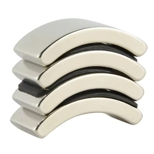
Arc-shaped magnets with a radius matched to the rotor curvature give a more sinusoidal air-gap flux distribution, which reduces cogging torque. Skewing the magnet or using multiple segments per pole also helps smooth out harmonics. A rectangular block magnet is easier to manufacture but often creates more torque ripple unless you spend extra effort on the pole shoe design.
We tell customers to consider samarium cobalt when the motor must survive sustained temperatures above 150°C, or when thermal stability is non-negotiable, like in aerospace or surgical robotics. Samarium cobalt has lower remanence than neodymium, so you lose some torque density, but its coercivity remains high even at 300°C. It also resists corrosion better, which matters in harsh environments without protective coatings.
One approach is to reduce waste in the magnet blank. We often suggest near-net-shape sintering or using thinner magnets with a higher-grade material instead of thicker lower-grade magnets. You can also optimize the magnet arc angle to minimize unused magnet material at the pole edges. Sometimes a small redesign, like moving from a full ring to segmented arcs, cuts cost more than trying to negotiate a cheaper grade.
Ask about their batch-to-batch consistency in remanence and coercivity, not just the minimum spec on a datasheet. A reputable supplier will provide actual magnetic test data for each production lot and can advise on coating durability against motor coolants. Also check whether they have experience with tight dimensional tolerances on arc segments, because even a 0.05 mm variation can affect the air gap and motor vibration.
Conclusion
Selecting the right magnet for a servo motor starts with torque demands rather than a blanket preference for rare earth or ferrite. A manufacturer will look at the actual operating point on the demagnetization curve, not just the room-temperature specs. When the windings heat up, a magnet that looks strong on paper can lose meaningful output if its intrinsic coercivity drops too steeply. That is why high-temperature grades of neodymium or samarium cobalt often win out in compact servos, while ferrite still makes sense for cost-sensitive designs with lower peak torque and moderate thermal loads. Beyond material chemistry, the physical form matters a great deal.
Segmenting the rotor into arc-shaped pieces rather than using a single ring reduces cogging torque and audible noise, which is critical in medical or robotics applications. Coatings play a dual role, preventing corrosion but also providing electrical isolation between laminations and magnets, especially in high-frequency drives. Finally, tight dimensional tolerances on magnet arcs ensure a consistent air gap and back-EMF waveform, leading to smoother commutation and less torque ripple. A manufacturer that balances these factors delivers a servo motor that holds its rated performance across temperature, speed, and load cycles.
Contact Us
Contact Person: Kelvin Lo
Email: [email protected]
Tel/WhatsApp: 0769-88561131
Website: https://dawamagnetic.com/