

RFID Chip Tag Factory Guide to High-Quality Tag Manufacturing
2026-11-16
The difference between an RFID tag that lasts five years and one that fails in five months often comes down to what happens on the factory floor. Yet most buyers never see that part of the process. This guide pulls back the curtain on high-quality RFID chip tag manufacturing—covering chip bonding, antenna materials, and the testing steps that separate premium tags from cheap imitations. Whether you're evaluating suppliers or refining your own production line, understanding these core practices will help you avoid costly field failures. At OSRFID, we build every tag around these principles, because quality isn’t inspected in—it’s manufactured in.
Chip Attachment Techniques That Endure Repeated Stress
Repeated thermal cycling creates shear stress at the die-to-substrate interface because silicon and organic laminates expand at very different rates. Underfill compounds absorb much of that strain, distributing it away from the solder bumps and preventing crack initiation at the outermost joints. For devices that see wide temperature swings, capillary underfill with a low coefficient of thermal expansion has become the baseline defense against early fatigue failure.
Solder alloy choice also shifts the failure mode. Standard SAC305 joints develop coarse intermetallic layers that embrittle after thousands of cycles, but additions of nickel, bismuth, or antimony refine the grain structure and slow crack propagation. Pairing those alloys with copper pillar bumps rather than conventional solder balls gives extra standoff height, which reduces the strain concentration at the neck of each connection and extends useful life under vibration and thermal shock.
For large die or packages with significant warpage, edge bonding and corner staking add mechanical anchors that keep the outermost bumps from peeling away. These adhesive fillets, often epoxy-based with silica fillers, resist the bending moments generated during board flex and drop events. The result is a more even load path across the entire bump array, so no single row of interconnects carries the full brunt of repeated stress.
Antenna Tuning for Metal and Liquid Proximity
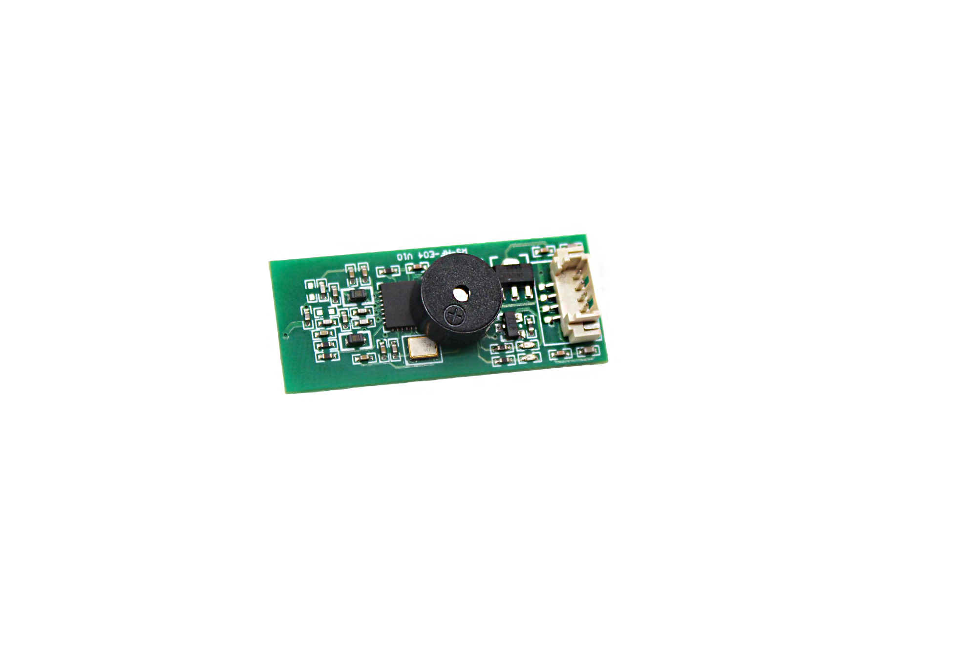
Metal surfaces within a wavelength or two of an antenna can reflect signals and create parasitic capacitance, pulling the resonant frequency down. The same thing happens when a device is placed near a bottle of water or held in a hand, because liquid and tissue have high dielectric constants. A match that looked fine on the bench often falls apart in actual use.
Most fixed matching networks are tuned for a single impedance curve. Once a metal table or a wet finger changes that curve, the return loss degrades and the radio either loses range or burns extra power retransmitting. Adaptive tuning helps by switching in different capacitor or inductor values on the fly, but it has to react quickly enough to keep up with movement.
A practical approach starts with measuring forward and reflected power at the antenna feed, then letting a control loop hunt for the lowest reflected level. With liquids, the detuning isn't just capacitive; it also loads the antenna resistively, so the target impedance shifts in more than one direction. Tuning tables combined with real-time sensing tend to work better than relying on a single static correction.
Substrate Materials Resistant to Chemicals and Sunlight
Chemical and sunlight resistance in substrate materials is not a single property but a combination of molecular stability, surface inertness, and UV absorption behavior. In industrial settings such as chemical processing plants, wastewater treatment facilities, and outdoor signage, the base layer must withstand prolonged contact with acids, alkalis, solvents, and intense solar radiation without cracking, delaminating, or fading. Traditional substrates like untreated wood or standard steel quickly degrade under these conditions, which is why engineered options are preferred for long-term installations.
Common choices include epoxy-based composites, which offer excellent adhesion and resistance to a broad range of chemicals, and polyurethane systems that add flexibility to handle thermal cycling alongside UV exposure. Fluoropolymers such as PVDF and PTFE provide near-inert surfaces against aggressive solvents and acids while also resisting photo-oxidation for decades outdoors. Ceramic and porcelain substrates, though heavier, bring inherent resistance to both chemical attack and sunlight without requiring organic topcoats. For lighter applications, fiberglass-reinforced panels with a gel coat formulated using hindered amine light stabilizers and UV absorbers deliver a practical balance of durability, weight, and cost. Selecting the right substrate often hinges on matching the specific chemical exposure profile with the expected UV intensity and service life of the installation.
Inline Quality Checks That Reveal Hidden Defects
Inline quality checks are often treated as a formality, a quick pass/fail gate that rarely catches anything beyond the most obvious flaws. But when you design them to actively probe for hidden defects — subtle material inconsistencies, micro-fractures from earlier processing, or tolerance drift that only appears under load — they become a completely different tool. The trick is to position these checks where defects are most likely to originate, not where they are easiest to spot. For example, measuring wall thickness immediately after a forming step can reveal thinning that polishing later disguises. Likewise, a quick hardness test right after heat treatment exposes soft spots that a final visual inspection would never flag.
The real value of inline checks comes from their ability to interrupt the process before a hidden defect becomes a shipped product. Instead of relying on a single inspection at the end of the line, you embed multiple small measurements that build a picture of each unit's health. A sudden change in surface conductivity during coating, a slight increase in pull force during assembly, or an unexpected vibration signature during a spin test — any one of these might be dismissed as noise. But tracked together, they reveal patterns that point straight to the source: a worn tool, contaminated material, or a fixture that has drifted out of alignment. Because the checks run continuously, operators can react within minutes rather than discovering the problem days later in a batch rejection.
To make inline checks genuinely revealing, you have to move beyond fixed thresholds. Hidden defects rarely announce themselves with a dramatic spike; they emerge as slow trends, small deviations that stay inside spec until they suddenly don't. By recording every measurement and comparing it to the unit's own baseline — not just the global tolerance — you can spot a drift that indicates a crack forming, a seal degrading, or a bond weakening. This approach turns each production run into a diagnostic session. Operators learn to read the subtle signatures of their equipment, and the line itself becomes the most sensitive inspection tool you own.
High-Precision Die Bonding for Consistent Read Range
Even a slight lateral shift during die attach can alter the parasitic capacitance between the chip and antenna pads, and that variation shows up directly as a wider spread in read distance across a production run. By locking placement tolerances to a few microns and keeping the adhesive fillet uniform, the coupling stays repeatable enough that individual tags no longer need to be tuned or binned by sensitivity.
On the line, automated optical inspection checks both position and tilt right after bonding, while the curing profile is adjusted for minimal die drift. The result is not just a tighter nominal read range but a batch-to-batch consistency that holds on metal, near liquids, or inside dense packaging, where impedance shifts would otherwise amplify any small assembly error.
Encoding Large Batches Without Slowing Production
When a large batch of video files lands on the server, the first instinct is often to push everything through the same encoding pipeline at once. That approach rarely ends well. CPU cores get saturated, storage I/O spikes, and the whole queue moves slower than expected. A better starting point is to split the batch into smaller chunks and run multiple encoding workers in parallel, but only up to the number of physical cores the machine can comfortably handle. Leaving one or two cores free for the operating system and file transfers makes a surprising difference in overall throughput.
Beyond raw parallelism, batch encoding stays fast when the queue is treated as a set of priorities rather than a simple first-in-first-out list. Short clips, urgent deliverables, or files that are already on local solid-state storage can be moved ahead while larger, less time-sensitive jobs wait. It also helps to let the encoder vary its settings depending on the source complexity, so simple screen recordings are processed with faster presets while high-motion footage gets the extra bitrate it needs. Finally, keep an eye on disk queue depth and network throughput. Encoding is rarely limited by the CPU alone, and a small drop in storage latency can often speed up the entire batch more than a more expensive processor would.
FAQ
It usually comes down to process control. Top-tier factories monitor every stage, from antenna printing to chip bonding, with real-time data rather than relying on end-of-line sampling. They also maintain tighter tolerances on conductive adhesive curing and placement accuracy, which directly affects read reliability.
Chip attachment. If the chip isn't aligned precisely with the antenna pads or the adhesive isn't cured correctly, impedance mismatch occurs and read range drops sharply. Factories that invest in automated optical inspection after bonding tend to catch these issues before they become batch-wide failures.
Not always. The right substrate depends on the application. A cheap PET inlay can perform beautifully in dry retail environments, while a costly polyimide substrate is overkill unless the tag faces high heat or chemical exposure. The key is matching substrate shrink rate and dielectric constant to the intended use, not just paying more.
Move from statistical sampling to 100% functional testing. Modern high-speed testers can encode and verify every tag on a reel without slowing production. Pairing that with proper ESD controls during chip handling and storage removes many of the random failures that only show up in the field.
Huge. Variations in ink thickness or edge sharpness change the antenna's resistance and resonant frequency. Factories that calibrate screen or gravure equipment daily, and check sheet resistance on every batch of conductive ink, produce tags with far less performance drift.
The chip is only part of the equation. Antenna geometry, substrate material, and assembly quality affect how well the chip and antenna are matched. Even minor differences in lamination pressure or adhesive thickness can shift the tag's frequency response enough to matter in dense reader environments.
Ask to see their process control charts, not just sample tags. Look for real-time monitoring of bonding force, curing temperature, and testing yield. A factory that can show you its reject rates by root cause is far more reliable than one that only shares a polished final report.
Humidity during chip bonding can cause micro-voids in the adhesive, leading to intermittent connections. Temperature swings during lamination affect how evenly the layers bond. High-quality factories control the production environment tightly and re-qualify materials when seasonal changes occur.
Conclusion
Manufacturing RFID tags that stand up to real-world use begins long before the final assembly line. Chip attachment techniques must be chosen for their ability to endure repeated mechanical stress—flexing, impact, and thermal cycling—without micro-fractures or loss of conductivity. This often means using advanced adhesives or solder alloys with matched thermal expansion, paired with underfill materials that cushion the die. Equally crucial is the substrate: it has to resist chemical spills, prolonged sunlight, and moisture ingress, otherwise the antenna traces degrade and the tag fails prematurely. In parallel, antenna tuning cannot be an afterthought. Tags mounted on metal surfaces or near liquids suffer from detuning, so engineers adjust the antenna geometry, add ferrite isolation layers, or use shorting structures to preserve a consistent read range across varied environments.
But durability alone isn't enough—quality and throughput define a competitive factory. High-precision die bonding is essential because even a slight misalignment of the chip relative to the antenna pads can cause impedance mismatches and weak backscatter signals, shrinking the effective read distance. Inline inspection systems need to catch hidden defects that visual checks miss: automated optical inspection, X-ray for void detection in solder joints, and RF coupling tests all work together to filter out marginal tags before they reach customers. On the encoding side, large batch programming should not become a bottleneck. Modern factories use parallel encoding stations with real-time database synchronization, so thousands of tags can be written with unique IDs at full line speed without duplicate serial numbers or data corruption, keeping both productivity and reliability high.
Contact Us
Contact Person: Esme Mo
Email: [email protected]
Tel/WhatsApp: 0086 191 2931 7837
Website: https://www.osrfidglobal.com/