

Precision Metal Bracket Factory Solutions That Simplify Custom Metal Fabrication
2026-11-19
Custom metal fabrication often gets bogged down in vague tolerances, long lead times, and brackets that almost fit. BOSI takes a different route: precision metal bracket factory solutions built around your exact specs, not the other way around. If you have ever lost days reworking a near-miss component, this look at our streamlined process will show you how a dedicated factory partner can simplify even the most stubborn bracket designs.
Laser-Cut Brackets That Arrive Ready to Weld or Mount
The usual routine with laser-cut parts is sorting, deburring, grinding, and fixing holes that never quite line up. These brackets skip that step. They come off the table with clean edges, consistent corner geometry, and mounting slots that are ready for hardware without a file or reamer in sight.
Weld seams land on bare, oxide-free edges, so there is no last-minute sanding just to get a decent arc start. The cut profile is smooth enough for direct fit-up against tube, plate, or extrusion, and the tolerances hold well enough that a fixture can be loaded the same way every time. On thinner gauges, the heat-affected zone stays predictable because the edge condition is uniform rather than hand-finished in patches.
For assembly work, that means less time spent making parts fit and more time actually welding or bolting them in place. If you are tired of treating fresh-cut brackets like rough castings, these are made to go straight from the box into the jig.
Bend Relief and Hole Placement Checked Before Production Starts
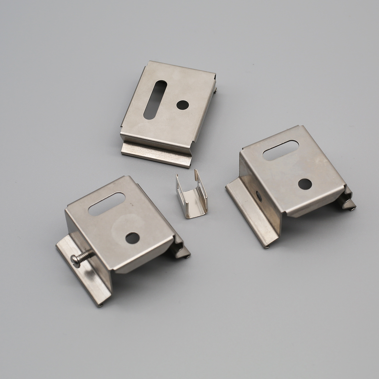
Before any part is sent to the floor, bend relief areas are reviewed against the actual tooling rather than a generic drafting rule. A relief cut that is too shallow or missing entirely can cause the material to tear at the corner during forming, and that damage often goes unnoticed until after finishing. Depth, width, and root radius are checked in relation to material grade and thickness, with extra attention given to bends that stop against a return flange or an adjacent face because those intersections pull differently under load.
Hole placement is examined in the same pass instead of being treated as a separate layout issue. Open features placed too close to a bend line tend to distort once the part is formed: round holes become oval, slots drift out of position, and narrow webs can buckle or crack. The safe setback depends on thickness, temper, and the actual bend radius, so the review avoids applying one fixed dimension across every part. When a feature needs to sit closer than normal, the sequence is adjusted or a small relief is added so the hole remains usable without extra rework.
Working through these points before production starts prevents problems that are far more expensive to correct after forming. Moving a hole slightly or adding a relief cut usually has no effect on fit or function, but tearing and distortion discovered after a run is complete often means scrapping the lot. Checking these details on the front end keeps the first articles closer to the intended finished part and reduces back-and-forth between engineering and the shop.
Powder Coating and Plating Done In-House to Keep Lead Times Short
Bringing powder coating and plating under our own roof changed how quickly we can move. Instead of waiting on outside vendors with unpredictable schedules, parts flow straight from fabrication into the finishing line. That means a bracket ordered on Tuesday can be coated, cured, and boxed by Thursday without the usual back-and-forth.
The real advantage shows up when a project shifts at the last minute. If a customer needs a different texture or a heavier zinc layer, our finishing team adjusts on the spot rather than reopening a purchase order. Keeping both processes in-house also lets us control thickness, adhesion, and edge coverage more consistently, so the finish matches the print instead of hoping a subcontractor paid attention.
Short lead times only matter if the parts arrive ready to use. By managing powder coating and plating side by side with machining and fabrication, we avoid damage from extra handling and eliminate the days lost to shipping between shops. The result is a cleaner handoff to assembly and a schedule that actually holds up.
Mixed Part Numbers Shipped in Assembly-Ready Kits
Ordering hardware for a multi-step build usually means juggling several line items and hoping the counts line up once everything arrives. These kits take a different route: mixed part numbers are pulled together, bagged, and packed so each workstation gets exactly what it needs for a defined production run. Instead of sorting through a dozen boxes on the floor, the team opens one container and starts the assembly sequence without pausing to hunt for a missing screw or spacer.
The real advantage shows up in fast-moving lines where changeovers happen often. A kit can follow a specific build sheet, carrying a mix of fasteners, brackets, standoffs, and small stamped parts in labeled compartments. This removes the guesswork from inventory staging and cuts down on the kind of errors that come from manually counting parts at the bench. When a set of part numbers is treated as a single unit, reordering also becomes cleaner, since consumption is tracked against the build quantity rather than against loose stock scattered across bins.
For contract manufacturers and internal assembly cells alike, the format shortens the distance between receiving and first torque. Kits arrive pre-checked against the bill of materials, so a quick visual scan confirms the break points between models or revisions. That predictability matters most on short-run jobs where a missing component can idle a line for hours. Mixed part numbers, handled this way, stop being a collection of loose SKUs and start behaving like one controlled input.
CAD File Reviews That Catch Tolerance Stack-Ups Early
Most tolerance stack-up failures don't start with a bad design—they start with a review that only looks at part geometry in isolation. A useful CAD file review pulls the assembly apart at the interfaces that matter: bearing seats, mating flanges, fastener patterns, and any place where two toleranced features have to share space. By sectioning the model and measuring from the same datums the machinist will use, you can catch a worst-case accumulation before it reaches the drawing set.
It helps to treat the CAD file as a working model rather than a finished picture. Move the components, suppress fasteners, check the stack in both directions, and look for spots where the nominal model hides a tight fit. When a chain of dimensions crosses several parts, color-mark the contributing features and step through the loop one link at a time. That approach turns a vague concern about tight tolerances into a specific list of features worth adjusting.
The earlier this happens, the cheaper the fix. Catching a stack-up during file review means changing a datum or opening up a clearance before tooling, procurement, or assembly planning has locked in. It also gives the team time to ask whether the tolerance scheme matches the manufacturing process, which is often where the real risk sits.
From Prototype to 10,000 Pieces Without Re-Tooling Delays
Moving from a first prototype to a full production run of 10,000 parts usually triggers hidden bottlenecks—tooling revisions, new approvals, re-quoting, and weeks of waiting. The core problem is that prototyping molds and production molds are treated as separate stages, so a design that works at low volume often needs fundamental changes before it can scale. A faster path is to design the initial tooling with production tolerances, steel grades, and gate locations from day one. This lets the same core tool insert survive early testing and later high-volume molding without being replaced or heavily modified.
The second shift is in how changes are managed. Instead of freezing the design after the prototype and then re-tooling when problems appear at scale, teams can use modular tooling with replaceable inserts for the few areas most likely to change—ribs, snap fits, bosses, or wall thickness zones. When a part needs adjustment after testing, only a small insert is machined, not the entire mold base. This keeps lead times at a few days rather than a few months, and it preserves the original tooling investment while the design matures.
Finally, process stability matters as much as tooling strategy. A mold that fills cleanly at 500 shots can behave very differently at 10,000 shots because of thermal expansion, wear, and material lot variation. Building in larger cooling channels, hardened ejector pins, and slightly wider process windows from the prototype phase means the same settings can be transferred to production with minimal tuning. When tooling and process are treated as one continuous curve rather than separate handoffs, scaling from prototype to 10,000 pieces becomes an incremental adjustment, not a re-tooling crisis.
FAQ
Most facilities handle a wide range, including mounting brackets, angle brackets, L-shaped and U-shaped supports, heavy-duty structural brackets, and small enclosures. The exact scope usually depends on the available laser cutting, punching, bending, and welding equipment.
It often starts with design feedback or a quick manufacturability review, then moves to prototypes before full runs. The factory may suggest standard hole patterns, bend radii, or material substitutions that reduce steps without changing function.
Carbon steel, stainless steel, aluminum, and sometimes galvanized or pre-coated sheet metal. Material choice is usually driven by load, corrosion exposure, finish requirements, and whether the part will be welded or assembled mechanically.
It depends on part size and process, but many shops hold ±0.005 inch on critical hole positions and ±0.010 inch on bend locations. Tighter tolerances are possible with CNC machining or secondary operations, though they add cost.
Common finishes include powder coating, e-coating, anodizing for aluminum, zinc or nickel plating, and passivation for stainless. The right finish usually balances corrosion protection, appearance, and the environment the bracket will face.
Drawings or CAD files, material preference, required quantity, finish, tolerances, and any critical dimensions. Photos of an existing part or a rough sketch can also work for early budgeting.
Many do. They may run low-quantity laser or turret punch parts for prototypes, then shift to hard tooling or automated bending once annual volumes justify it.
First article inspection, dimensional checks with calipers or CMM, thread gauge testing if hardware is installed, and visual checks for burrs, scratches, or coating defects. Some jobs also receive a small batch sample approval.
Conclusion
Getting a bracket order right usually comes down to details that never make it onto a render. That is where this factory approach changes the workflow. Instead of sending a file into a queue and hoping for the best, each CAD model is reviewed before anything hits the laser. Bend relief, hole placement, and tolerance stack-ups are checked early, so the parts that arrive are not just dimensionally close but actually ready to weld or mount. That step alone removes most of the back-and-forth that normally eats up a week. Cutting happens on lasers that hold clean edges, and because powder coating and plating are handled in-house, there is no handoff to an outside finisher. The result is a shorter lead time without the usual chase for status updates.
The same practicality carries through to how orders leave the dock. Mixed part numbers are packed into assembly-ready kits, so a build cell can start immediately instead of sorting through loose cartons. Prototype runs are not treated as a separate, slow lane; the process moves from a handful of samples to 10,000 pieces without re-tooling delays. That matters when purchasing is trying to keep a project on schedule. It also means design changes do not force a complete start-over. The factory's focus stays on taking the friction out of custom metal fabrication rather than asking customers to manage a chain of suppliers. For brackets that need to fit the first time and ship in a usable sequence, this setup genuinely simplifies the work.
Contact Us
Contact Person: Kristy Wu
Email: [email protected]
Tel/WhatsApp: 8613826954049
Website: https://www.dgbosi.com/